Tuesday, November 27, 2007

Great Circuit for Highly Isolated Floating Power Supply

Every so often you have an application where you need to provide power to a circuit that is floating at high voltage. In general, isolated power supplies can be an expensive, complex endeavor. Sometimes undesirable effects, such as substantial ripple injected into the powered circuit can cause problems. In EDN Design Ideas, November 22, 2007 issue, there is a circuit for a floating power supply that can withstand a separation of 10cm between the ground section and the floating section. This flexibility can come in very handy. I might consider a changes with the bridge rectifier diodes, and I might consider some protective components if the output section is floating at a very high voltage.

For details on this excellent idea, please see EDN Design Ideas: Wireless “battery” energizes low-power devices

Labels: , ,

Tuesday, November 20, 2007

Isolated signal measurement

It's often useful to measure voltages that are floating at a high voltage. One technique is to use analog to digital converters, feed the digital signals into fiber optic links, then digital to analog converters (or just use the digital signals) at ground level. This can also be done with voltage-to-frequency converters and frequency-to-voltage converters. Other techniques include capacitive pick up, transformers, etc. Linear optoisolators can be used in some applications. There are a few manufacturers that can make them, or you can assemble your own. There is an application note from Agilent that can provide additional information.

For less voltage isolation, other techniques can be used, such as isolation amplifiers.

There are a few commercially available devices provide isolated voltage measurement.

Labels:

Thursday, November 8, 2007

High Voltage Resistor Types

Once the resistor voltage rating goes above a few hundred volts, there are very few manufacturers to choose from. The main types of high voltage resistors are:

  • Surge high voltage resistors, which are used in series with circuit elements that might experience arcs or intentional transients. Examples include resistors in series with an arc lamp or the resistor in an RC filter since they will need to carry current due to arcs.
  • Precision resistors (used for high voltage dividers). Typically these are thin film resistors.
  • General purpose high voltage resistors, generally thick film. Compared to precision high voltage resistors, these are not as stable, have worse voltage coefficients, worse temperature coefficients, and worse tolerances. However, they are lower cost and can be rated at higher power. Applications include high voltage dividers where precision is not important, load resistors and bleeder resistors.

More than with low voltage resistors, it is important to select a high quality manufacturer to obtain a part with good performance and reliability. Also, it is important in many applications to specify non-inductive types.

Labels:

Wednesday, November 7, 2007

Built-in Protection for Voltage Regulator

Whenever working with high voltage systems, there is a concern that components may fail during an arc or other transient event. Generally much care must be taken when selecting components, adding protective parts such as tranzorbs, and in defining the layout. Linear Technology has introduced an "overvoltage protection regulator" which might be useful. Since regulators seem to be vulnerable to the effects of high voltage transients, this is a welcome addition.

Maximum input voltage is 100V, and maximum output voltage is 80V. While this can come in handy, it is also good to know that for lower voltage operation, there is a wide safety margin.

The regulator has built-in protection for -30V or reverse input voltage, and it also has an inrush current limiter.

In applications where electronic systems must cope with high voltage surges of short duration, the LT4356 provides solid front-end protection for valuable, safety critical downstream components.

Labels: , ,

Monday, November 5, 2007

Water Forms Floating Bridge at High Voltage

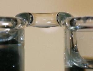
When exposed to a high-voltage electric field, water in two beakers climbs out of the beakers and crosses empty space to meet, forming the water bridge. The liquid bridge, hovering in space, appears to the human eye to defy gravity.


Upon investigating the phenomenon, the scientists found that water was being transported from one beaker to another, usually from the anode beaker to the cathode beaker. The cylindrical water bridge, with a diameter of 1-3 mm, could remain intact when the beakers were pulled apart at a distance of up to 25 mm.
Can you think of a practical use? If so, please let us know!

These excerpts are from an article at http://www.physorg.com/news110191847.html which contains additional details on this phenomenon.

Friday, November 2, 2007

Additional Test Methods for Dielectric Testing

The previous post provided test methods for dielectric breakdown and dielectric strength at commercial ac frequencies, i.e., 60Hz. Here are two additional test methods to be used for dc testing and impulse testing.

IEC 60243-2 gives requirements additional to those in IEC 60243-1 for the determination of the electric strength of solid insulating materials under direct voltage stress.

For impulse testing, see IEC 60243-3, which gives requirements additional to those in IEC 60243-1 for the determination of the electric strength of solid insulating materials under 1,2/50 ms impulse voltage stress.

For reference:
IEC 60243-2 Electric Strength of Insulating Materials - Test Methods - Part 2: Additional Requirements for Tests Using Direct Voltage

IEC 60243-3 Electric Strength of Insulating Materials - Test Methods - Part 3: Additional Requirements for 1,2/50 us Impulse Tests

Labels: , ,

Standard Test Methods for Dielectric Breakdown Voltage and Dielectric Strength

Standards that applies to testing for dielectric breakdown and dielectric strength are from ASTM and the IEC.

ASTM test method D 149 is most commonly used to determine the dielectric breakdown voltage through the thickness of a test specimen (puncture). It may also be used to determine dielectric breakdown voltage along the interface between a solid specimen and a gaseous or liquid surrounding medium (flash-over).

This test method is similar to IEC Publication 60243-1. All procedures in this method are included in IEC 60243-1. Differences between this method and IEC 60243-1 are largely editorial. Gives test methods for the determination of the short-time electric strength of solid insulating materials at power frequencies between 48 Hz and 62 Hz. It does not consider the testing of liquids and gases. It does, however, include methods for the determination of breakdown voltages along the surfaces of solid insulating materials are included.

Test method D 149 is not intended for use in determining intrinsic dielectric strength, direct-voltage dielectric strength, or thermal failure under electrical stress (see Test Method D 3151). That test method covers the determination of the thermal failure of solid electrical insulating materials subjected to electric stress at commercial power frequencies.

For reference:

ASTM D 149 REV A: Standard Test Method for Dielectric Breakdown Voltage and Dielectric Strength of Solid Electrical Insulating Materials at Commercial Power Frequencies

ASTM D 3151: Standard Test Method for Thermal Failure of Solid Electrical Insulating Materials under Electric Stress

IEC 60243-1: Electrical Strength of Insulating Materials - Test Methods - Part 1: Tests at Power Frequencies

Labels: , ,